


Patent claim for a new type of shuttering magnet
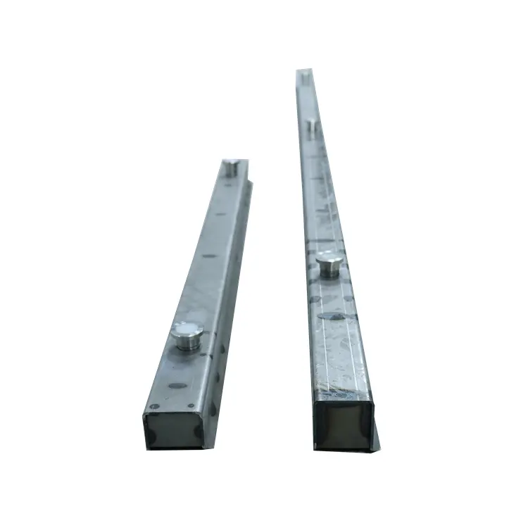
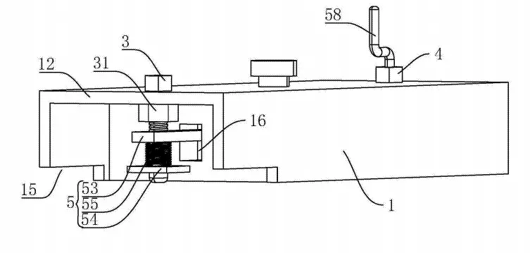
1.A magnetic box fixer, characterized in that: it includes a C-shaped non-magnetic fixing frame (1), the bottom surface of the non-magnetic fixing frame (1) is provided with a magnet groove (11), the magnet groove (11) is provided with a permanent magnet (2), the two ends of the non-magnetic fixing frame (1) are hollowed out, one end of the non-magnetic fixing frame (1) is provided as a clamping end (12), and the other end is provided as a supporting end (13), and the clamping end (12) and the supporting end (13) are respectively located on both sides of the magnet groove (11).
2.A magnetic box fixer according to claim 1, characterized in that: a rectangular pressing opening (15) is provided on the bottom surface of the clamping end (12), a clamping bolt (3) is inserted into the clamping end (12), a clamping nut (31) is provided at the clamping end (12), and the clamping bolt (3) is screwed to the clamping nut (31).
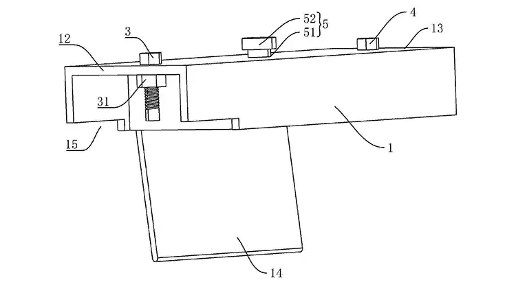
3.A magnetic box fixer according to claim 2, characterized in that: a supporting bolt (4) is inserted into the supporting end (13), a supporting nut (41) is provided at the supporting end (13), and the supporting bolt (4) is screwed to the supporting nut (41).
4.A magnetic box fixer according to claim 3, characterized in that: the depth of the magnet slot (11) is greater than the thickness of the permanent magnet (2), and a lifting mechanism (5) for driving the permanent magnet (2) to rise and fall in the magnet slot (11) is provided between the non-magnetic fixing frame (1) and the permanent magnet (2).
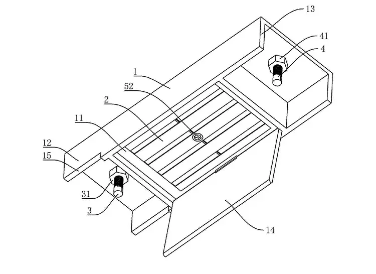
5.A magnetic box holder according to claim 4, characterized in that: the inner top wall of the magnet slot (11) is provided with a weak magnetic coating, the lifting mechanism (5) comprises a through hole (51) arranged on the non-magnetic fixing frame (1), the through hole (51) is connected to the magnet slot (11), a pull rod (52) is passed through the through hole (51), one end of the pull rod (52) is fixedly connected to the permanent magnet (2), and the other end passes through the through hole (51).
6.A magnetic box holder according to claim 4, characterized in that: vertically arranged through grooves (16) are respectively provided on both side walls of the magnet groove (11), and the magnet groove (11) is respectively connected to the clamping end (12) and the supporting end (13) through the corresponding through grooves (16); the lifting mechanism (5) comprises two synchronous rods (53), one of which passes through the through groove (16) and is fixedly connected to the permanent magnet (2) at one end, and is slidably connected to the clamping bolt (3) at the other end; the clamping bolt (3) is provided with a first limit plate (54), and the clamping bolt (3) is sleeved with a first return spring (55), one end of the first return spring (55) is in contact with the first limit plate (54), and the other end is in contact with the corresponding synchronous rod (53); the other synchronous rod (53) passes through the through groove (16) and is fixedly connected to the permanent magnet (2) at one end, and is slidably connected to the supporting bolt (4) at the other end; the supporting bolt (4) is provided with a first limit plate (54), a second return spring (57) is sleeved on the support bolt (4), one end of the second return spring (57) contacts the second limit plate (56), and the other end contacts the corresponding synchronization rod (53).
7.A magnetic box fixer according to claim 6, characterized in that: the first limit plate (54) is threadedly connected to the clamping bolt (3), and the second limit plate (56) is threadedly connected to the support bolt (4).
8.A magnetic box fixer according to claim 6 or 7, characterized in that: the cross-section of the bottom end of the support bolt (4) is arc-shaped.
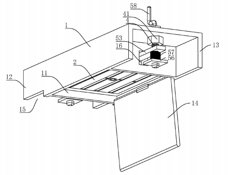
9.A magnetic box fixer according to claim 8, characterized in that: an I-shaped crank (58) is fixed to the top of the support bolt (4).
10.A magnetic box fixer according to claim 1, characterized in that: a cover plate (14) is hingedly connected to the bottom edge of the magnet slot (11), and a weak magnetic coating is coated on the side of the cover plate (14) facing the permanent magnet (2).