

Explanation of the Utility Model Patent for Shuttering Magnet
The purpose of this utility model is to provide a magnetic box holder, which has the advantages of being convenient for fixing the formwork support and reducing damage to the formwork.
The above - mentioned technical purpose of this utility model is achieved through the following technical solutions:
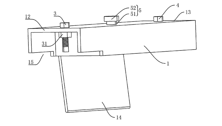
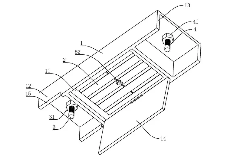
A magnetic box holder includes a non - magnetic fixing frame arranged in a C - shape. The bottom surface of the non - magnetic fixing frame is provided with a magnet groove, and a permanent magnet is arranged in the magnet groove. Both ends of the non - magnetic fixing frame are hollow - out. One end of the non - magnetic fixing frame is set as a pressing end, and the other end is set as a supporting end. The pressing end and the supporting end are respectively located on both sides of the magnet groove.
By adopting the above - mentioned technical solution, when it is necessary to fix the formwork support, the non - magnetic fixing frame is placed on the edge of the formwork support, and the pressing end of the non - magnetic fixing frame is pressed onto the formwork support. The permanent magnet and the formwork are attracted by magnetic force, and the supporting end is tightly pressed against the formwork to form a compression on the formwork support. When it is necessary to remove the magnetic box holder, it is only necessary to lift the supporting end, and then the magnetic box holder can be removed.
Further, the bottom surface of the pressing end is provided with a rectangular pressing opening, a pressing bolt is inserted through the pressing end, a pressing nut is arranged on the pressing end, and the pressing bolt is screwed with the pressing nut.
By adopting the above - mentioned technical solution, the pressing opening is buckled on the edge of the formwork, so that other parts of the bottom surface of the non - magnetic fixing frame can be attached to the formwork, thereby forming a more stable compression on the formwork support.
Further, a supporting bolt is inserted through the supporting end, a supporting nut is arranged on the supporting end, and the supporting bolt is screwed with the supporting nut.
By adopting the above - mentioned technical solution, the supporting bolt is tightly pressed against the plate, so that the supporting end and the formwork form multi - point support, the support is more stable, and the side force on the supporting end can be reduced, and its service life can be extended.
Further, the depth of the magnet groove is greater than the thickness of the permanent magnet, and a lifting mechanism for driving the permanent magnet to rise and fall in the magnet groove is arranged between the non - magnetic fixing frame and the permanent magnet.
By adopting the above - mentioned technical solution, when it is necessary to compress the formwork support, the lifting mechanism drives the permanent magnet to expose out of the magnet groove, so that the permanent magnet can be closely attracted to the formwork. When it is necessary to remove the non - magnetic fixing frame, the permanent magnet is retracted into the magnet groove through the lifting mechanism.
Further, the top wall of the magnet groove has a weak magnetic coating, and the lifting mechanism includes a through - hole arranged on the non - magnetic fixing frame. The through - hole is connected to the magnet groove, and a pull rod is inserted through the through - hole. One end of the pull rod is fixedly connected with the permanent magnet, and the other end passes through the through - hole.
By adopting the above - mentioned technical solution, when it is necessary to separate the permanent magnet from the formwork, the permanent magnet is pulled by the pull rod, so that the permanent magnet is attracted to the top wall in the magnet groove, thereby avoiding the permanent magnet from slipping out of the magnet groove.
Further, the two side walls of the magnet groove are respectively provided with vertically arranged through grooves. The magnet groove is respectively connected to the pressing end and the supporting end through the corresponding through grooves. The lifting mechanism includes two synchronous rods. One of the synchronous rods passes through one end of the through groove and is fixedly connected with the permanent magnet, and the other end is slidably connected with the pressing bolt. A first limit plate is arranged on the pressing bolt, and a first return compression spring is sleeved on the pressing bolt. One end of the first return compression spring is in contact with the first limit plate, and the other end is in contact with the corresponding synchronous rod; the other synchronous rod passes through one end of the through groove and is fixedly connected with the permanent magnet, and the other end is slidably connected with the supporting bolt. A second limit plate is arranged on the supporting bolt, and a second return compression spring is sleeved on the supporting bolt. One end of the second return compression spring is in contact with the second limit plate, and the other end is in contact with the corresponding synchronous rod.
By adopting the above - mentioned technical solution, when the permanent magnet is separated from the formwork, the first compression spring and the second compression spring simultaneously contact the corresponding synchronous rods, and the synchronous rods are forced to lift the permanent magnet, and the permanent magnet is restricted in the magnet groove.
Further, the first limit plate is threadedly connected with the pressing bolt, and the second limit plate is threadedly connected with the supporting bolt.
By adopting the above - mentioned technical solution, the position of the first limit plate on the pressing bolt and the position of the second limit plate on the supporting bolt can be adjusted to change the compression amount of the first compression spring and the second compression spring, thereby changing the elastic force of the first compression spring and the second compression spring.
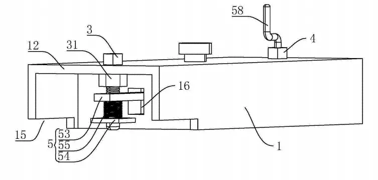
Further, the bottom end cross - section of the supporting bolt is arc - shaped.
By adopting the above - mentioned technical solution, the permanent magnet can be separated from the plate by screwing the supporting bolt.
Further, an L - shaped crank is fixedly arranged at the top end of the supporting bolt.
By adopting the above - mentioned technical solution, the crank is convenient for workers to rotate the supporting bolt without additional devices.
Further, the edge of the bottom surface of the magnet groove is hinged with a cover plate, and the side surface of the cover plate facing the permanent magnet is coated with a weak magnetic coating.
By adopting the above - mentioned technical solution, when the magnetic box holder is not in use, the cover plate is attracted to the permanent magnet, avoiding the permanent magnet from attracting other sundries.
In conclusion, this utility model has the following beneficial effects:
It is convenient for fixing the formwork support, not only easy to use, but also reducing damage to the formwork;
Through the setting of the lifting mechanism, it is convenient to drive the permanent magnet to extend and retract in the magnet groove;
Through the setting of the cover plate, when the magnetic box holder is not in use, the cover plate is attracted to the permanent magnet, avoiding the permanent magnet from attracting other sundries.
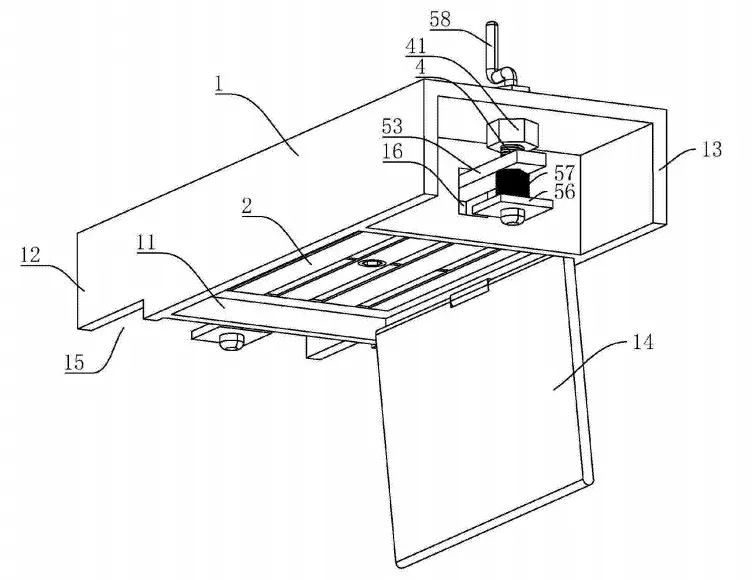
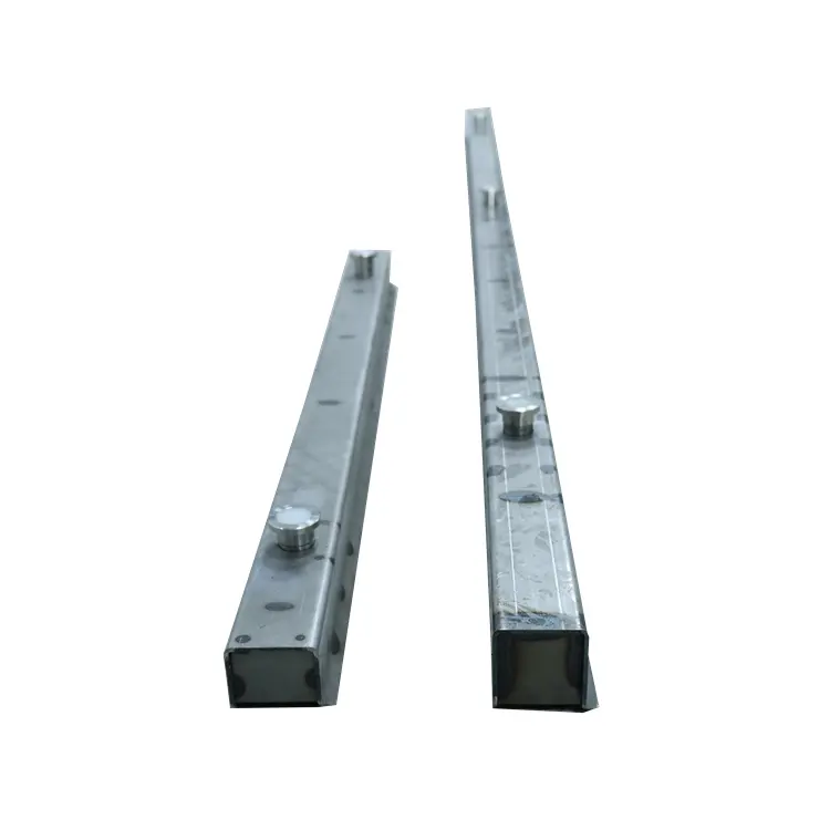
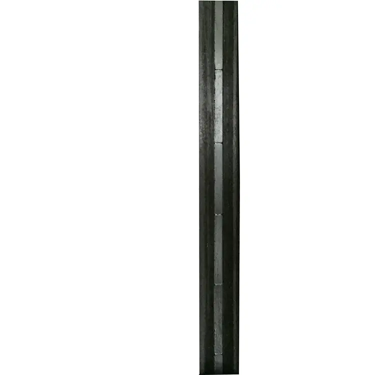
Illustration of the Drawings Figure 1 is a schematic diagram of the magnetic box holder in Example 1; Figure 2 is a schematic diagram for showing the bottom of the magnetic box holder in Example 1; Figure 3 is a schematic diagram for showing the magnetic box holder in Example 2; Figure 4 is a schematic diagram for showing the bottom of the magnetic box holder in Example 2.
In the figures, 1. Non - magnetic fixing frame; 11. Magnet groove; 12. Pressing end; 13. Supporting end; 14. Cover plate; 15. Pressing opening; 16. Through groove; 2. Permanent magnet; 3. Pressing bolt; 31. Pressing nut; 4. Supporting bolt; 41. Supporting nut; 5. Lifting mechanism; 51. Through - hole; 52. Pull rod; 53. Synchronous rod; 54. First limit plate; 55. First return compression spring; 56. Second limit plate; 57. Second return compression spring; 58. Crank.